|
 |
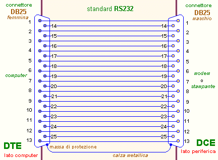
lato DTE |
Direzione |
lato DCE |
 |
| pin |
Descrizione |
Descrizione |
pin |
| 1 |
Protective Ground |
- |
Protective Ground |
1 |
| 2 |
Transmitted Data |
[DTE>DCE] |
Received Data |
2 |
| 3 |
Received Data |
[DCE>DTE] |
Transmitted Data |
3 |
| 4 |
Request To Send |
[DTE>DCE] |
Clear To Send |
4 |
| 5 |
Clear To Send |
[DCE>DTE] |
Request To Send |
5 |
| 6 |
Data Set Ready |
[DCE>DTE] |
Data Set Ready |
6 |
| 7 |
Signal Ground |
- |
Signal Ground |
7 |
| 8 |
Data Carrier Detect |
[DCE>DTE] |
Data Carrier Detect |
8 |
| 9 |
Reserved |
- |
Reserved |
9 |
| 10 |
Reserved |
- |
Reserved |
10 |
| 11 |
Unassigned |
- |
Unassigned |
11 |
| 12 |
Secondary Data Carrier
Detect |
[DCE>DTE] |
Secondary Data Carrier
Detect |
12 |
| 13 |
Secondary Clear To Send |
[DCE>DTE] |
Secondary Request To Send |
13 |
| 14 |
Secondary Transmitted Data |
[DTE>DCE] |
Secondary Received Data |
14 |
| 15 |
Transmission
Element Timing |
[DCE>DTE] |
Transmission Element
Timing |
15 |
| 16 |
Secondary Received Data |
[DCE>DTE] |
Secondary Transmitted Data |
16 |
| 17 |
Receiver Element
Timing |
[DCE>DTE] |
Receiver Element Timing |
17 |
| 18 |
Local Loopback |
[DTE>DCE] |
Local Loopback |
18 |
| 19 |
Secondary Request To Send |
[DTE>DCE] |
Secondary Clear To Send |
19 |
| 20 |
Data Terminal Ready |
[DTE>DCE] |
Data Terminal Ready |
20 |
| 21 |
Remote LoopBack |
[DTE>DCE] |
Remote LoopBack |
21 |
| 22 |
Ring Indicator |
[DCE>DTE] |
Ring Indicator |
22 |
| 23 |
Data Signal Rate Selector |
[DTE>DCE] |
Data Signal Rate Selector |
23 |
| 24 |
Transmitter Element
Timing |
[DTE>DCE] |
Transmitter Element Timing |
24 |
| 25 |
Test Mode |
[DCE>DTE] |
Test Mode |
25 |


